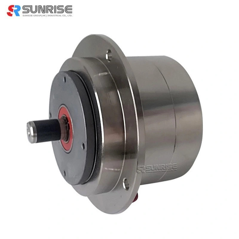
PMC Magnetic Particle Clutch Micro Series Shaft
Fig.1 Magnetic particle clutch structure diagram (typical example)
Micro magnetic particle clutch structure and principle of operation
● The Micro magnetic particle clutch structure is shown in Fig. 1. The drive member linked to the input side and the driven member linked to the output side are disposed concentrically across a powder gap.
● The powder gap is filled with powder (magnetic iron powder), and the coil for passing a magnetic flux to the powder is built in the stator, and it is designed to feed direct current from outside through the lead wire.
● While the drive member is rotating, when a current flows in the coil, a magnetic flux is generated as indicated by broken line in the drawing, and the powder is linked like a chain along the magnetic flux, and its coupling force the driven member is driven, and the torque is transmitted to the output side.
● When the exciting current is cut off, the magnetic flux disappears, and the coupling force of the powder is eliminated, thereby cutting of transmission of powder to the driven member.
Magnetic particle clutch
|
Model |
PMC-5 |
PMC-10 |
PMC-20 |
PMC-50 |
PMC-100 |
|
|
Rated torque[kgf-m](N-m) |
0.05(0.5) |
0.1(1) |
0.2(2) |
0.5(5) |
1(10) |
|
|
Capacity |
Current(A) |
0.35 |
0.47 |
0.55 |
0.8 |
1.0 |
|
Power(W) |
8.4 |
11.3 |
13 |
19 |
24 |
|
|
No. of hours set(S) |
0.02 |
0.03 |
0.055 |
0.055 |
0.09 |
|
|
Moment of inertia (kgcm2)
|
Input side |
2.1*10-1 |
3.45*10-1 |
6.80*10-1 |
1.83 |
5.3 |
|
Output side |
1.7*10-2 |
4.6*10-2 |
1.03*10-1 |
4.0*10-1 |
1.1 |
|
|
Weight(kg) |
0.67 |
0.88 |
1.27 |
2.3 |
4.1 |
|
|
Area of heat release(cm)2 |
350 |
|||||
|
Maximum speed (r/min) |
1800 |
|||||
|
Micro magnetic particle clutch dimension(unit:mm) |
|||||
|
|
|||||
|
Model |
PMC-5 |
PMC-10 |
PMC-20 |
PMC-50 |
PMC-100 |
|
L1 |
77 |
83 |
95 |
111 |
113 |
|
L2 |
16.5 |
18.5 |
22.5 |
25 |
32 |
|
L3 |
8.5 |
8.5 |
9.5 |
12 |
15 |
|
L4 |
4 |
4 |
4 |
4 |
5 |
|
L5 |
13.5 |
16 |
19.5 |
22 |
29 |
|
L6 |
28.5 |
29.5 |
34 |
37.5 |
46 |
|
L7 |
5.5 |
5.5 |
6.5 |
6 |
7 |
|
e1 |
10.5 |
12 |
15 |
18 |
24 |
|
e2 |
20 |
16 |
13 |
10 |
9 |
|
D1 |
70 |
76 |
85 |
100 |
128 |
|
D2 |
114 |
90 |
75 |
66 |
60 |
|
D3 |
50 |
56 |
65 |
80 |
98 |
|
D4(h7) |
48 |
54 |
63 |
78 |
98 |
|
D5(h7) |
40 |
42 |
48 |
60 |
80 |
|
D6 |
30 |
34 |
40 |
50 |
70 |
|
d(g6) |
5 |
7 |
9 |
12 |
15 |
|
T |
4.5 |
6.5 |
8.5 |
11.5 |
16.5 |
Magnetic Particle Clutch Mounting
(1) Fasten the fitting part of the mounting flange to the mounting plate and fix it.
(2) Always use an elastic coupling to connect the micro magnetic particle clutch and load shaft, and set the concentricity, perpendicularity, etc. of the shafts at this time within the allowable value of the elastic
coupling to be used.
(3) When mounting a pulley or the like, ensure it is within the range of allowable shaft load.
(4) The heat dissipation area of the mounting plate should be at least 350 cm2 or more.
(5) Pay attention to the length of the mounting screw on the input side (using a screw of the depth or more described in the external dimensions may damage the internal bearing).
Micro magnetic particle clutches exciting current VS torque
Magnetic particle clutch application
Magnetic particle clutches idling torque
Even if the exciting current is interrupted completely, idling torque is generated due to mechanical losses arising from residual magnetism of the powder, grease of the bearing, and friction such as a seal.
Magnetic particle brakes cannot perform torque control below this idling torque.
In the case of magnetic particle clutches, idling torque refers to the torque caused by the output shaft when forced to rotate while being dragged by the input shaft (dragged torque). Magnetic particle clutches, like magnetic particle brakes, cannot perform torque control below this torque.
Since this idling torque depends on the model, refer to the specifications of each model.
Application scenarios
Others for magnetic particle clutch
(1) In the product (magnetic particle clutches and magnetic particle brakes) having a three-digit figure attached to the model’s name such as 001 in PMC-5-001, the mounting dimensions, voltage and other conditions are special, and may differ from the description herein, but the basic operation and handling cautions are common.
(2) The structural diagrams are representative examples, and may differ depending on the model and options including the specification. Inquire us for details.


