


Sunrise High Performance YSHY Industrial Hysteresis brake for Cable Production tension controlling
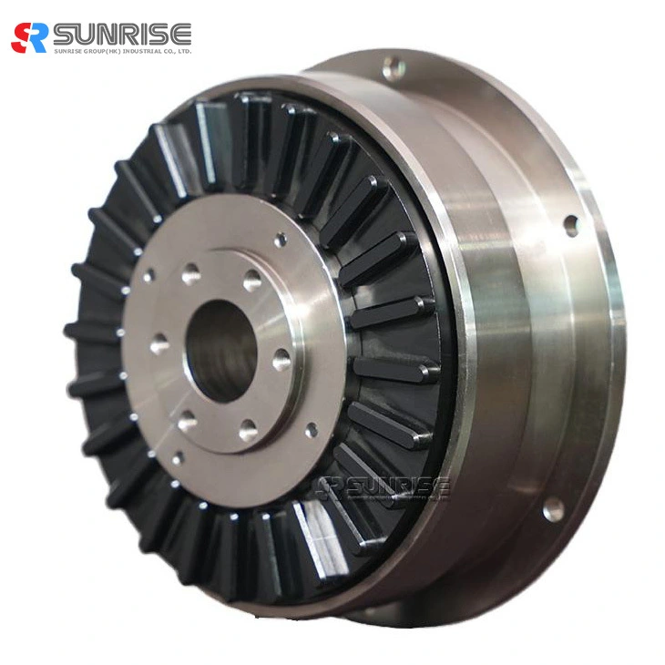
Fig. 1 Structural diagrams of YSHY hysteresis brake (representative examples)
Hysteresis brake structure and principle of operation
● Figures 1 show typical structures of hysteresis brake.
● The hysteresis brake is formed by fixing a stator and a first rotor.
Hysteresis Brake Feature
Specification
|
Model No. |
YSHY-1A |
YSHY-2A |
YSHY-4A |
YSHY-6A |
|
Rated Torque (Nm) |
1 |
2 |
4 |
6 |
|
Power Consumption(75°C) (W) |
90 |
120 |
180 |
230 |
|
Max Voltage (V) |
24 |
24 |
24 |
24 |
|
Rated resistance (Ω) |
27 |
22 |
17 |
13 |
|
Max speed (rpm) |
3000 |
3000 |
3000 |
1800 |
|
Weight (kg) |
4 |
8.5 |
10.5 |
17 |
|
Hysteresis brake dimension (unit: mm) |
|||||
|
Model No. |
YSHY-1A |
YSHY-2A |
YSHY-4A1 |
YSHY-6A |
|
|
Installation |
L1 |
65 |
80 |
83 |
101 |
|
L2 |
62 |
76 |
79 |
97 |
|
|
L3 |
5 |
7 |
7 |
10 |
|
|
L4 |
3 |
4 |
4 |
4 |
|
|
L5 |
3 |
4 |
4 |
4 |
|
|
D1 |
136 |
180 |
180 |
222 |
|
|
D2 |
124 |
166 |
166 |
205 |
|
|
D3(h7) |
112 |
140 |
140 |
130 |
|
|
D4 |
115 |
162 |
162 |
192 |
|
|
D5 |
60 |
84 |
84 |
105 |
|
|
D6(h7) |
40 |
60 |
60 |
65 |
|
|
D7 |
30 |
50 |
50 |
52 |
|
|
M |
6-M5 |
6-M6 |
6-M5 |
6-M5 |
|
|
S |
5.5 |
6.5 |
6.5 |
6.5 |
|
|
d |
18 |
30 |
40 |
40 |
|
hysteresis brake exciting current VS torque
Hysteresis brake Operation
● Never touch the product during operation
● Never increase the rotating speed more than allowable.
● Use thermometer when measuring temperature.
Hysteresis clutch|brake application
Application scenarios
Cautions on Safety for hysteresis clutch and hysteresis brake