


Power on flange mounted FCD electromagnetic clutch
Power on flange mounted FCD electromagnetic clutch
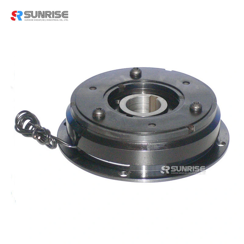
The power on flange mounted electromagnetic clutch (also known as electromagnetic power on clutch) transmits drive when the coil is energized. The flange mounted electromagnetic clutch can be engaged statically and dynamically and is available in various sizes, torques and multipole high torque versions.
Used to transmit rotary motion when the electrical power is turned on, the flange mounted electromagnetic clutch and can be supplied with various armature styles to suit the intended design layout. These consist of an armature plate and return spring, an integral hub with a bore and key way or, with internal bearings.
The high torque variant (multi-pole) gives a higher static torque within a smaller envelope size reducing overall weight, wear and the number of start/stops required by the primary motor therefore improving motor life.
Feauture
Specification
|
Electromagnetic clutch data |
|||||||||||||||
|
MODEL |
FCD-1(-2)-006 |
FCD-1(-2)-015 |
FCD-1(-2)-025 |
FCD-1(-2)-050 |
FCD-1(-2)-100 |
FCD-1(-2)-200 |
FCD-1(-2)-400 |
||||||||
|
Static Torque[kgf-m](N- m) |
0.6(0.6) |
1.5(15) |
2.5(25) |
5.0(50) |
10(100) |
20(200) |
40(400) |
||||||||
|
Dynamic Torque[kgf-m](N-m) |
0.5(5) |
1.0(10) |
2.0(20) |
4.0(40) |
8(80) |
16(160) |
32(320) |
||||||||
|
Power[DC24V](W)at20°C |
11 |
15 |
20 |
25 |
35 |
45 |
60 |
||||||||
|
Weight(kg) |
0.66(0.5) |
1.19(0.91) |
2.11(1.66) |
3.8(3.05) |
6.9(5.4) |
13(10.5) |
23.6(18.7) |
||||||||
|
Maximum speed(r/min) |
1800 |
||||||||||||||
|
|
|||||||||||||||
|
Radius |
A |
63 |
80 |
100 |
125 |
160 |
200 |
250 |
|||||||
|
B |
67.5 |
85 |
106 |
133 |
169 |
212.5 |
264 |
||||||||
|
C1 |
80 |
100 |
125 |
150 |
190 |
230 |
290 |
||||||||
|
B |
67.5 |
85 |
106 |
133 |
175 |
215 |
270 |
||||||||
|
C2 |
72 |
90 |
112 |
137 |
175 |
215 |
270 |
||||||||
|
C3 |
35 |
42 |
52 |
62 |
80 |
100 |
125 |
||||||||
|
D1 |
12 |
15 |
15 |
20 |
20 |
25 |
25 |
30 |
30 |
40 |
40 |
50 |
50 |
60 |
|
|
D2 |
12 |
15 |
20 |
25 |
30 |
40 |
50 |
||||||||
|
E1 |
26 |
31 |
41 |
49 |
65 |
83 |
105 |
||||||||
|
E2 |
33 |
37 |
47 |
52 |
62 |
74.5 |
101.5 |
||||||||
|
F |
23 |
28.5 |
40 |
45 |
62 |
77 |
100 |
||||||||
|
S |
38 |
45 |
55 |
64 |
75 |
90 |
115 |
||||||||
|
U |
39.5 |
47 |
57 |
67 |
78 |
93.5 |
118.5 |
||||||||
|
Y |
5 |
6 |
7 |
7 |
9.5 |
9.5 |
11.5 |
||||||||
|
Shaft |
H |
24 |
26.5 |
30 |
33.5 |
37.5 |
44 |
51 |
|||||||
|
J |
3.5 |
4.3 |
5 |
5.5 |
6 |
7 |
8 |
||||||||
|
K |
2 |
2.5 |
3 |
3.5 |
4 |
5 |
6 |
||||||||
|
L1 |
43 |
51 |
61 |
70.5 |
84.5 |
100.5 |
118 |
||||||||
|
L2 |
31.5 |
35 |
41 |
46.5 |
53.5 |
64.5 |
75 |
||||||||
|
L3 |
51.5 |
60 |
71 |
86.5 |
103.5 |
124.5 |
145 |
||||||||
|
M1 |
22 |
24 |
27 |
30 |
34 |
40 |
47 |
||||||||
|
M2 |
15 |
20 |
25 |
30 |
38 |
45 |
54 |
||||||||
|
N1 |
20 |
25 |
30 |
40 |
50 |
60 |
70 |
||||||||
|
N2 |
2 |
2 |
3 |
2 |
3 |
5 |
6 |
||||||||
|
P |
7.5 |
8 |
9 |
9 |
11.5 |
13 |
15.5 |
||||||||
|
T |
6 |
8 |
10 |
12 |
15 |
18 |
22 |
||||||||
|
W |
4 |
5 |
5 |
7 |
7 |
10 |
12 |
||||||||
|
Z1 |
4-90° |
||||||||||||||
|
Z2 |
60° |
45° |
30° |
45° |
225° |
||||||||||
|
m1 |
2-M4 |
2-M5 |
2-M5 |
2-M6 |
2-M8 |
2-M8 |
2-M10 |
||||||||
|
m2 |
3M4*0.7P*4L l |
3M4*0.7P*6L |
4-M4*0.7P*8L |
6-M5*0.8P*8L |
4-M6*1P*12L |
4-M6*1P*12L |
|||||||||
|
X |
1.5 |
1.8 |
2.1 |
2.8 |
3.4 |
4.5 |
5.1 |
||||||||
|
a |
0.2(±0.05) |
0.3(+0.05/-0.1) |
0.5(-0/-0.2) |
||||||||||||
|
b |
4 |
5 |
5 |
7 |
7 |
10 |
12 |
||||||||
|
t1 |
1.8 |
2.3 |
2.3 |
2.3 |
2.3 |
3.3 |
3.3 |
3 |
3.3 |
3.8 |
3.8 |
3.8 |
3.8 |
5 |
|
|
t2 |
1.8 |
2.3 |
2.3 |
3.3 |
3.3 |
3.8 |
3.8 |
||||||||
Application scenarios