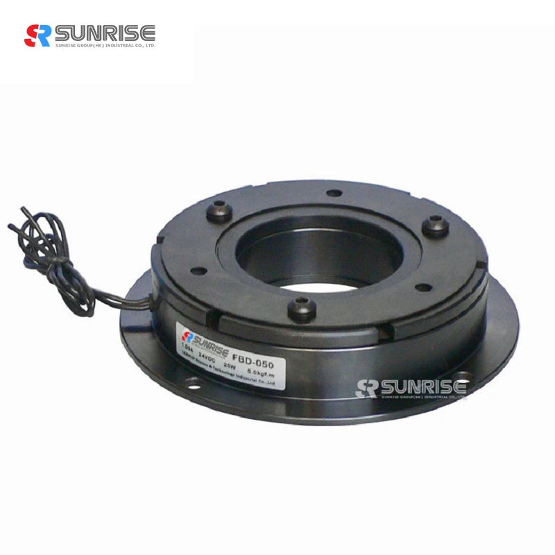
FBD power on electromagnetic brake
FBD power on electromagnetic brake
In order to generate the torque, a DC voltage is applied to the coil via the connection cable. The resulting magnetic field acts over the air gap on the armature plate and attracts the plate against the force of the prestressed spring towards the friction lining of the rotor. The torque is transmitted by friction. The power on electromagnetic clutch is switched off by interrupting the voltage supply. Because of the missing magnetic force, the pring pulls the armature plate back to its original position. The power on electromagnetic clutch is released free of residual-torque..
Feauture
Electromagnetic brake operation principle
Permanent magnetic brake designed for industrial and mobile applications. Brake force is produced via magnets which reduce both size and weight of brake versus spring applied brakes. Armature is mounted via springs which eliminates backlash. Standard brakes can accommodate temperatures up to 140deg C. Brakes can be tuned to provide a controlled stop. Output assemblies easily modified to fit your application
Specification
|
Electromagnetic brake data |
|||||||||||||||
|
MODEL |
FBD-2-006 |
FBD-2-015 |
FBD-2-025 |
FBD-2-050 |
FBD-2-100 |
FBD-2-200 |
FBD-2-400 |
||||||||
|
Static Torque[kgf-m](N-m) |
0.6(0.6) |
1.5(15) |
2.5(25) |
5.0(50) |
10(100) |
20(200) |
40(400) |
||||||||
|
Dynamic Torque[kgf-m](N-m) |
0.5(5) |
1.0(10) |
2.0(20) |
4.0(40) |
8(80) |
16(160) |
32(320) |
||||||||
|
Power[DC24V](W)at20°C |
11 |
15 |
20 |
25 |
35 |
45 |
60 |
||||||||
|
Weight(kg) |
0.32 |
0.58 |
1.07 |
1.97 |
3.45 |
7.1 |
12.2 |
||||||||
|
Maximum speed(r/min) |
1800 |
||||||||||||||
|
|
|||||||||||||||
|
Radius |
A1 |
63 |
80 |
100 |
125 |
160 |
200 |
250 |
|||||||
|
A2 |
46 |
60 |
76 |
95 |
120 |
158 |
210 |
||||||||
|
A3 |
34.5 |
41.5 |
51.5 |
61.5 |
79.5 |
99.5 |
124.5 |
||||||||
|
C1 |
80 |
100 |
125 |
150 |
190 |
230 |
290 |
||||||||
|
C2 |
72 |
90 |
112 |
137 |
175 |
215 |
270 |
||||||||
|
C3 |
35 |
42 |
52 |
62 |
80 |
100 |
125 |
||||||||
|
V1 |
3-3.1 |
3-4.1 |
3-5.1 |
3-6.1 |
3-8.1 |
3-10.2 |
3-12.2 |
||||||||
|
V2 |
3-6.3 |
3-8 |
3-10.5 |
3-12 |
3-15 |
3-18 |
4-22 |
||||||||
|
V3 |
3-6 |
3-7 |
3-9 |
3-10.5 |
3-14 |
3-17 |
4-19 |
||||||||
|
D |
12 |
15 |
15 |
20 |
20 |
25 |
25 |
30 |
30 |
40 |
40 |
50 |
50 |
60 |
|
|
E |
26 |
31 |
41 |
49 |
65 |
83 |
105 |
||||||||
|
Y |
5 |
6 |
7 |
7 |
9.5 |
9.5 |
11.5 |
||||||||
|
Shaft |
H |
18 |
20 |
22 |
24 |
26 |
30 |
35 |
|||||||
|
J |
3.5 |
4.3 |
5 |
5.5 |
6 |
7 |
8 |
||||||||
|
K |
2 |
2.5 |
3 |
3.5 |
4 |
5 |
6 |
||||||||
|
L |
22 |
24.5 |
28 |
31 |
35 |
41.5 |
48 |
||||||||
|
L1 |
37 |
44.5 |
53 |
61 |
73 |
86.5 |
102 |
||||||||
|
L2 |
25.5 |
28.5 |
33 |
37 |
42 |
50.5 |
59 |
||||||||
|
M |
15 |
20 |
25 |
30 |
38 |
45 |
54 |
||||||||
|
P |
7.5 |
8 |
9 |
9 |
11.5 |
13 |
15.5 |
||||||||
|
T |
6 |
8 |
10 |
12 |
15 |
18 |
22 |
||||||||
|
X |
1.5 |
1.8 |
2.1 |
2.8 |
3.4 |
4.5 |
5.1 |
||||||||
|
Z |
6-60° |
8-45° |
|||||||||||||
|
m |
2-M4 |
2-M5 |
2-M6 |
2-M8 |
2-M10 |
||||||||||
|
a |
4 |
5 |
5 |
5 |
5 |
7 |
7 |
7 |
7 |
10 |
10 |
12 |
12 |
15 |
|
|
t |
1.8 |
2.3 |
2.3 |
2.3 |
2.3 |
3.3 |
3.3 |
3.3 |
3.3 |
3.8 |
3.8 |
3.8 |
3.8 |
5 |
|
Application scenarios


