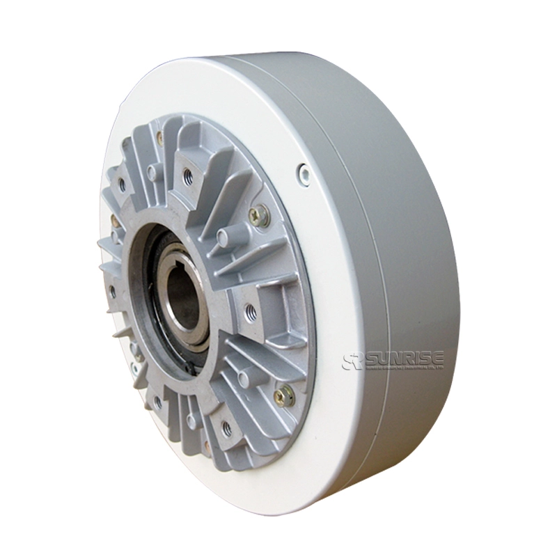
Stable torque through shaft type PBO magnetic powder brake
Fig. 1 Structural diagrams of PB series magnetic powder brake (representative examples)
Magnetic powder brake structure and principle of operation
● The magnetic powder brake structure is shown in Fig. 1. The drive member linked to the shaft and the stator are disposed concentrically across a powder gap.
● The powder gap is filled with powder (magnetic iron powder), and the coil for passing a magnetic flux to the powder is built in the stator, and it is designed to feed direct current from outside through the lead wire.
● When a current flows in the coil, a magnetic flux is generated as indicated by broken line in the drawing, and the powder is linked like a chain along the magnetic flux, and by this coupling force a brake torque equivalent to the current is generated.
● When the exciting current is cut off, the magnetic flux disappears, and the coupling force of the powder is eliminated, thereby setting the drive member free.
magnetic powder brake Feature
Specification
|
Magnetic powder brake datasheet |
||||||||
|
Model |
PBO-006 |
PBO-015 |
PBO-025 |
PBO-050 |
PBO-100 |
PBO-200 |
PBO-400 |
|
|
Rated torque [kgf](N-m)[ |
0.6(6) |
1.2(12) |
2.5(25) |
5(50) |
10(100) |
20(200) |
40(400) |
|
|
Capacity |
Current (A) |
0.5 |
0.6 |
0.8 |
1.0 |
1.2 |
1.8 |
2.5 |
|
Power (W) |
7.2 |
9.4 |
17.5 |
22.6 |
28.8 |
45.6 |
70 |
|
|
No. of hour set (S) |
0.10 |
0.10 |
0.12 |
0.13 |
0.25 |
0.37 |
0.4 |
|
|
Moment of inertia(kgcm2) |
1.55*10-3 |
5.55*10-3 |
9.4*10-3 |
2.3*10-2 |
6.6*10-2 |
2.0*10-1 |
4.6*10-1 |
|
|
Weight |
2.7 |
5.2 |
9 |
14.5 |
37 |
53 |
106 |
|
|
Maximum speed r/min |
1500 |
1000 |
||||||
|
Weight of powder (g) |
14 |
25 |
39 |
60 |
117 |
255 |
370 |
|
| Magnetic powder brake dimension(unit:mm) | |||||||
|
Model |
PBO-006 |
PBO-015 |
PBO-025 |
PBO-050 |
PBO-100 |
PBO-200 |
PBO-400 |
|
L1 |
68 |
70 |
79 |
96 |
118 |
132 |
156 |
|
L2 |
3 |
3 |
3 |
3 |
3 |
3 |
5 |
|
L3 |
5.5 |
6 |
7.5 |
8 |
9 |
11 |
13 |
|
D1 |
126 |
152 |
172 |
220 |
258 |
298 |
370 |
|
D2 |
75 |
82 |
105 |
130 |
150 |
180 |
200 |
|
D3(g7) |
42 |
65 |
90 |
110 |
120 |
150 |
160 |
|
d(H7) |
12 |
16 |
25 |
30 |
35 |
45 |
50 |
|
w(F7) |
5 |
6 |
8 |
8 |
10 |
14 |
14 |
|
n-R*depth |
6-M5*8L |
6-M6*9L |
6-M6*9L |
6-M6*10L |
6-M6*12L |
6-M10*12L |
6-M12*19L |
Magnetic Powder Brake Mounting
(1) Fasten the fitting part of the bracket to the mounting plate and fix it.
(2) Always use an elastic coupling to connect the magnetic powder brake shaft and load shaft, and set the concentricity, perpendicularity, etc. of the shafts at this time within the allowable value of the elastic coupling to be used.
(3) When mounting a pulley or the like, ensure it is within the range of allowable shaft load
Powder clutch|brake Application
Magnetic powder brake slip rotation speed vs. torque characteristics
As showing below, the slip rotation speed vs. torque characteristics when the current is set as a parameter. If the exciting current is kept constant, torque can be kept constant irrespective of the slip rotation speed (the difference in rotational speed between the drive member and driven member). This is because powder (magnetic iron powder), which is also called semisolid, is used as a medium for power transmission. In other words, this characteristic means that there is no difference between the static friction torque and dynamic friction torque, indicating the ease of torque control.
This characteristic not only allows continuous slip and increases the heat capacity but also widens the scope of application of magnetic powder clutches and brakes such as for tension control and buffer startup.
In the case of tension control, for example, the slip rotation speed of the magnetic powder clutch/brake changes according to the reel diameter, but this characteristic enables simple and accurate control merely by controlling.
Application scenarios
Magnetic Powder Brake Allowable Connection Workload
When starting or braking loads with inertia with the clutch or brake, the powder and working surface slip and generate frictional heat. This heat generation raises the temperature of each part of the magnetic powder clutch/brake as well as the powder itself. If the heat generation is excessive, the temperature of the friction part rises abnormally. To prevent this problem, an allowable connection workload is determined for each model. The magnetic powder clutch/brake should, therefore, be used within this range.


