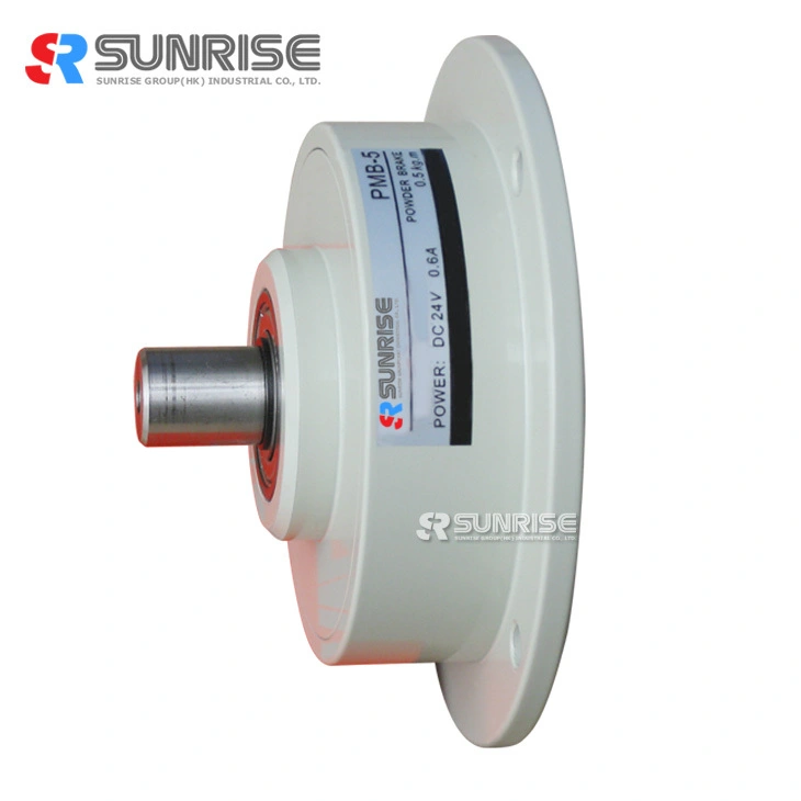
Compact design micro series PMB magnetic particle brake
Fig.1 Magnetic particle brake structure diagram (typical example)
Micro magnetic particle brake structure and Feature
1. Continuous slip operation
The powder enables continuous slip on the working surface as well as stable transmission torque regardless of the slip rotation speed.
However, the powder must be used within the permissible continuous heat dissipation.
2. Stable torque
Due to the shape of the operating surface and powder leakage prevention structure, the powder keeps functioning normally and therefore stable torque can be reproduced
3. Smooth connection and drive
With almost equal coefficients of static and dynamic friction, load-based acceleration/ deceleration can be obtained without shock at the time of complete connection
Magnetic particle Brake Data
|
Model |
PMB-5 |
PMB-10 |
PMB-20 |
PMB-50 |
|
|
Rated torque[kgf-m](N-m) |
0.05(0.5) |
0.1(1) |
0.2(2) |
0.5(5) |
|
|
Capacity |
Current(A) |
0.35 |
0.42 |
0.5 |
0.6 |
|
Power(W) |
8.4 |
10 |
12 |
14 |
|
|
No. of hours set(S) |
0.02 |
0.03 |
0.04 |
0.05 |
|
|
Moment of inertia(kgcm2) |
9.4*10-3 |
2.7*10-2 |
5.52*10-2 |
1.25*10-1 |
|
|
Weight(kg) |
0.4 |
0.54 |
0.96 |
1.3 |
|
|
Area of heat release(cm)2 |
350 |
||||
|
Maximum speed (r/min) |
1800 |
||||
|
Model |
PMB-5 |
PMB-10 |
PMB-20 |
PMB-50 |
|
L1 |
45 |
50 |
59 |
99 |
|
L2 |
40 |
43 |
50 |
55 |
|
L3 |
5 |
7 |
9 |
11 |
|
L4 |
4 |
4 |
5 |
5 |
|
L5 |
3 |
4 |
6 |
8 |
|
L6 |
14 |
17 |
21 |
27 |
|
L7 |
10 |
12 |
15 |
18 |
|
L9 |
3 |
4 |
5 |
8 |
|
D1 |
70 |
76 |
90 |
108 |
|
D2 |
60 |
66 |
80 |
95 |
|
D3 |
50 |
56 |
70 |
82 |
|
D4 |
24 |
36 |
40 |
44 |
|
D5(g7) |
24 |
30 |
40 |
44 |
|
d(g7) |
5 |
7 |
9 |
15 |
|
T |
4.5 |
6.5 |
8.5 |
14 |
|
R |
4.5 |
4.5 |
4.5 |
6 |
Magnetic Particle Brake Mounting
(1) Fasten the fitting part of the mounting flange to the mounting plate and fix it.
(2) Always use an elastic coupling to connect the brake shaft and load shaft, and set the concentricity, perpendicularity, etc. of the shafts at this time within the allowable value of the elastic coupling to be used.
(3) When mounting a pulley or the like, ensure it is within the range of allowable shaft load.
(4) The heat dissipation area of the mounting plate should be at least 350cm2.
Micro magnetic particle brake exciting current VS torque
Magnetic particle Brake application
Magnetic particle Brake Allowable connection workload
When starting or braking loads with inertia with the clutch or brake, the powder and working surface slip and generate frictional heat.
This heat generation raises the temperature of each part of the clutch/brake as well as the powder itself. If the heat generation is excessive, the temperature of the friction part rises abnormally. To prevent this problem, an allowable connection workload is determined for each model. The clutch/brake should, therefore, be used within this range.
Application scenarios


