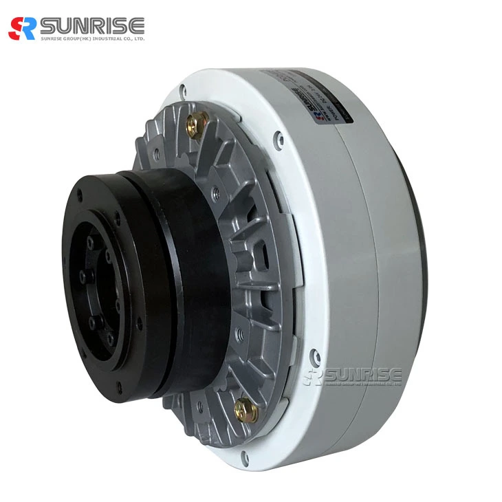
Magnetic Powder Clutch/Brake 6Nm-200Nm
Structural diagrams of PCO series magnetic powder clutches
(representative examples)
Magnetic powder clutch Structure and principle of operation
● The magnetic powder clutch structure is shown in Fig. 1. The drive member linked to the input side and the driven member linked to the output side are disposed concentrically across a powder gap.
● The powder gap is filled with powder (magnetic iron powder), and the coil for passing a magnetic flux to the powder is built in the stator, and it is designed to feed direct current from outside through the lead wire.
● While the drive member is rotating, when a current flows in the coil, a magnetic flux is generated as indicated by broken line in the drawing, and the powder is linked like a chain along the magnetic flux, and its coupling force the driven member is driven, and the torque is transmitted to the output side.
● When the exciting current is cut off, the magnetic flux disappears, and the coupling force of the powder is eliminated, thereby cutting of transmission of powder to the driven member.
magnetic powder clutch Feature
Magnetic Powder clutch Specification
| Model | PCO-006 | PCO-015 | PCO-025 | PCO-050 | PCO-100 | PCO-200 | PCO-400 | |
| Rated Torque[kgf-m](N-m) | 0.6(6) | 1.2(12) | 2.5(25) | 5(50) | 10(100) | 20(200) | 40(400) | |
|
Capacity |
Current (A) | 0.9 | 1.0 | 2.0 | 2.3 | 2.5 | 2.5 | 3.0 |
| Power (W) | 17.8 | 21.6 | 26.4 | 33.6 | 48 | 60 | 82 | |
| No. of hour set(S) | 0.10 | 0.10 | 0.12 | 0.13 | 0.25 | 0.37 | 0.4 | |
| Moment of inertia (kgcm2) | Input side | 2.70*10-3 | 6.3*10-3 | 1.2*10-2 | 2.6*10-2 | 7*10-2 | 2.1*10-1 | 2.41*10-1 |
| Output side | 5.0*10-4 | 1.1*10-3 | 2.3*10-3 | 5.8*10-3 | 1.5*10-2 | 5.0*10-2 | 2.2*10-1 | |
| Maximum speed (r/min) | 1500 | 1000 | ||||||
| Weight of powder (g) | 14 | 25 | 39 | 60 | 117 | 255 | 370 | |
|
Magnetic powder clutch dimension(unit:mm) |
|||||||
|
|
|||||||
|
Model |
PCO-006 |
PCO-015 |
PCO-025 |
PCO-050 |
PCO-100 |
PCO-200 |
PCO-400 |
|
L1 |
110 |
126 |
122 |
155 |
177 |
197 |
239 |
|
L2 |
8 |
9 |
10 |
12 |
14 |
15 |
18 |
|
L3 |
44 |
49 |
51 |
64 |
77 |
83 |
91 |
|
L4 |
3 |
3 |
4 |
4 |
8 |
9 |
7 |
|
L5 |
13 |
14 |
15 |
17 |
20 |
21 |
25 |
|
L6 |
24 |
29 |
26 |
36 |
45 |
42 |
42 |
|
D1 |
140 |
152 |
186 |
220 |
290 |
336 |
398 |
|
D2 |
100 |
105 |
115 |
140 |
180 |
190 |
210 |
|
D3(g7) |
85 |
90 |
100 |
120 |
150 |
170 |
180 |
|
D4 |
75 |
80 |
85 |
105 |
130 |
150 |
160 |
|
d(H7) |
16 |
20 |
25 |
30 |
35 |
45 |
50 |
|
W(F7) |
5 |
6 |
8 |
8 |
10 |
14 |
14 |
|
d1* depth |
M5*8L |
M6*9L |
M6*10L |
M6*12L |
M10*14L |
M10*15L |
M12*18L |
|
d2*depth |
M5*10L |
M6*12L |
M6*12L |
M6*14L |
M10*15L |
M10*16L |
M12*19L |
Magnetic powder clutch mounting
● Provide the fin rotation stop screw with a clearance in the axial direction as well as on the side hole of the fin detent plate (arranged by customer) (see the enlarged view).
Tightening the fin applies excessive force to the bearings inside the magnetic powder clutch and may quickly damage the bearings.
● Be careful of the length of the fin rotation stop screw. If the fin rotation stop screw is too long, the tip of the screw may interfere with the bracket (rotating part).
● Always use an elastic coupling to connect the input side and shaft, and set the concentricity, perpendicularity, etc. of the shafts at this time within the allowable value of the elastic coupling. Provide the elastic coupling with a thrust play.
Installation without thrust play will cause a bearing failure (noise, locking, etc.) inside the clutch.
● When using a pulley drive, observe the range of allowable axial load and do not overstretch the belt. Failure to do so may cause a bearing failure (noise, locking, etc.)
● Since the outer periphery rotates, be sure to cover the whole body with a wire mesh or the like with good ventilation.
Magnetic Powder Clutch Application
Application scenarios
Attention Of Operation For Magnetic Powder Clutch
● Magnetic powder clutches allowable continuous heat dissipation. Although the magnetic powder clutch/brake can be used in continuous slip mode, the temperature of magnetic powder clutch/brake parts including powder rises due to the heat generated by slip. To solve this problem, an allowable continuous heat dissipation is provided for each model, and the magnetic powder clutch/brake needs to be used within that range.
● Note that the allowable continuous heat dissipation differs depending on the cooling method: natural cooling, forced air cooling, or other means. The rated value is shown for each model, but be careful regarding natural cooling as the value varies depending on the input rotation speed.
CAUTION for magnetic powder clutch


