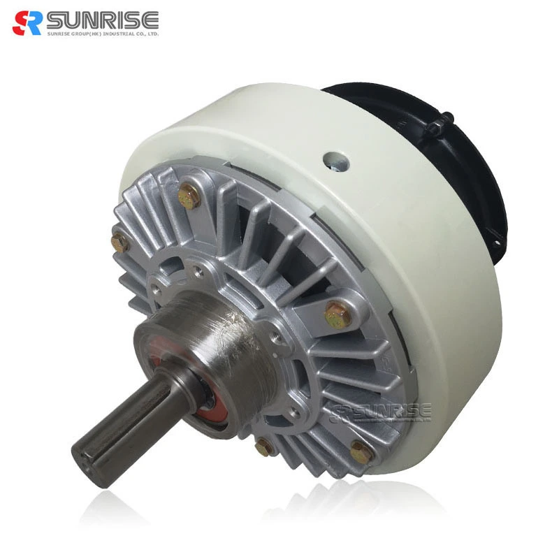
Single shaft type PFB magnetic powder brake with fan
Fig. 1 Structural diagrams of PB series magnetic particle brake
Magnetic powder brake and Working principle
The magnetic powder brake structure is shown in Fig. 1. The drive member linked to the input side and the driven member fixed on the stator are disposed concentrically across a powder gap.
● The powder gap is filled with powder (magnetic iron powder), and the coil for passing a magnetic flux to the powder is built in the stator, and it is designed to feed direct current from outside through the lead wire.
● While the drive member is rotating, when a current flows in the coil, a magnetic flux is generated as indicated by broken line in the drawing, and the powder is linked like a chain along the magnetic flux, so that the drive member and driven member are coupled together. Since the driven member is fixed on the stator, it works as a brake.
● When the exciting current is cut off, the magnetic flux disappears, and the coupling force of the powder is eliminated, thereby cutting of transmission of powder to the driven member..
magnetic powder brake Feature
Specification
|
Magnetic powder brake datasheet |
||||||
|
Model |
PFB-025 |
PFB-050 |
PFB-100 |
PFB-200 |
PFB-400 |
|
|
Rated torque[kgf-m](N-m) |
2.5(25) |
5(50) |
10(100) |
20(200) |
40(400) |
|
|
Capacity |
Current(A) |
1.24 |
2.15 |
2.4 |
2.7 |
3.5 |
|
Power (W) |
29.8 |
51.5 |
57.6 |
64.8 |
84 |
|
|
No. of hours set (S) |
0.12 |
0.13 |
0.25 |
0.37 |
0.4 |
|
|
Moment of inertia(kgcm2) |
3.8*10-3 |
9.5*10-3 |
3.5*10-2 |
9.15*10-2 |
2.4*10-1 |
|
|
Weight |
7.6 |
15.5 |
34 |
45 |
99 |
|
|
Maximum speed (r/min) |
1800 |
|||||
|
Weight of powder (g) |
33 |
60 |
140 |
225 |
370 |
|
| Magnetic particle brake dimension(unit:mm) | |||||
|
Model |
PFB-025 |
PFB-050 |
PFB-100 |
PFB-200 |
PFB-400 |
|
D1 |
182 |
219 |
278 |
327 |
395 |
|
D2 |
160 |
196 |
160 |
174 |
230 |
|
D3 |
78 |
100 |
140 |
150 |
200 |
|
D4(g7) |
55 |
74 |
100 |
110 |
130 |
|
L1 |
227 |
265 |
326 |
366 |
473 |
|
L2 |
163 |
175 |
226 |
257 |
334 |
|
L3 |
64 |
91 |
100 |
109 |
139 |
|
L4 |
17 |
30 |
28 |
30 |
35 |
|
L5 |
43 |
55 |
65 |
69 |
92 |
|
L6 |
62 |
62 |
62 |
62 |
98 |
|
d(h7) |
20 |
25 |
30 |
35 |
45 |
|
T |
22 |
28 |
33 |
38.5 |
48.5 |
|
W(p7) |
5 |
7 |
7 |
10 |
12 |
|
V |
M5*0.8P*10L |
M6*1P*12L |
M10*1.5P*20L |
||
|
R |
M5 |
M6 |
6-M10*1.5P*20L |
8-M10*1.5P*15L |
|
|
S |
1/8 |
1/4 |
3/8 |
||
Magnetic Powder Brake Mounting
(1) Fasten the fitting part of the bracket to the mounting plate and fix it.
(2) Always use an elastic coupling to connect the magnetic particle brake shaft and load shaft, and set the concentricity, perpendicularity, etc. of the shafts at this time within the allowable value of the elastic coupling to be used.
(3) When mounting a pulley or the like, ensure it is within the range of allowable shaft load
powder brake exciting current VS torque
Powder clutch | brake application
Application scenarios


